What is the working process of PE foam bag making machine?

PE foam bag making machine is a kind of equipment used to produce foam bags. It converts PE foam film into finished bags through a series of process steps. So how to use PE foam bag making machine to produce foam bags?

PE foam bag making machine

Raw material preparation: First, prepare PE foam film as raw material. These films are usually formed into films by heating and melting PE particles in an extruder.


Film extrusion: The preheated PE particles are placed in the extruder, where the particles are extruded through a high-temperature and high-pressure extrusion head to form a continuous PE foam film.


Film cooling: At the outlet of the extrusion head, the hot film is quickly cooled by a cooling roller or a cold air system to solidify into a PE foam film.


Cutting and winding: The cooled foam film enters the cutting device and is cut according to the size requirements of the bag. Then, the cut bag is wound into a roll by the winding device to facilitate the subsequent bag making operation.


Bag making: The cut foam film roll is loaded into the bag making machine, and the edges of the film are heated and sealed through the heating and sealing device to form the shape of a foam bag. Next, the bottom of the bag is sealed, and some other operations (such as punching, cutting, etc.) are optionally performed.


Finishing: After the above process steps, the PE foam bag is produced. It can be used to package various products, such as electronic products, toys, household items, etc. The foam material plays a cushioning and protective role in the packaging to ensure that the product is not damaged during transportation and storage.


The use of PE foam bag making machine not only greatly improves the production efficiency of the bag, but also ensures the consistency and quality of the bag. It is widely used in the packaging industry, providing high-quality foam bags for all walks of life to meet the packaging needs of users. If you have the purchase needs of PE foam bag making machine, you can contact Fuliyuan, we are the leading PE foam bag making machine manufacturer in China, trustworthy!

How to solve glue gun leakage

1. Glue leakage at the Hot melt gluing nozzle 

If glue leaks from the nozzle during glue spraying, the possible reasons are as follows:

a. The temperature of the glue gun is not enough. The temperature of the hot melt glue gun should be increased appropriately.

b. If the pressure or flow rate of the air jet is too small, glue will drip from the nozzle. Increase the pressure of the air blowing pipe appropriately.

c. If the air passage in the nozzle is blocked, remove the nozzle module and clean it.


2. If glue leaks from the nozzle when the machine is not spraying glue, the possible reasons are as follows:

a. The thimble does not completely close the glue channel, and it is necessary to increase the pressure on the air channel of the solenoid valve of the glue gun.

b. The ejector pin is damaged and needs to be replaced.

c. The ejector pin and the outlet of the glue channel do not cooperate well. Adjust the fine-tuning bolt on the ejector pin to press down on the ejector pin and then loosen the bolt. Manually operate the solenoid valve on the glue gun several times.


3. The small hole in the middle of the needle valve leaks glue.

a. The sealing ring underneath the needle valve needs to be replaced.

hot glue fiber nozzle


hot glue spraying gun

hot glue machine

Why should we clean pur hot melt hose regularly?(1)

Generally, after half a year or a year of use, the glue pipeline of the PUR hot melt adhesive machine needs to be cleaned and maintained.


What are the advantages of regular maintenance?


It can increase the fluidity of glue and improve the glue effect.


1. Ensure the quality of PUR hot melt adhesive


Clean pipes can prevent PUR hot melt adhesive from remaining, solidifying or deteriorating in the pipes, ensuring that the PUR hot melt adhesive is fresh every time it is used. This is particularly important for application scenarios that require high-precision bonding to ensure the stability of product quality.


2. Improve production efficiency


Pipe cleaning can avoid production interruptions due to blockages and reduce downtime. The smooth glue feeding process can ensure the continuous operation of the production line and improve production efficiency.


3. Extend equipment life


Residue in pipes can cause corrosion or wear on the inner walls of pipes, and regular cleaning can reduce this damage. Well-maintained equipment generally has a longer service life, reducing equipment replacement costs.


4. Reduce failure rate and maintenance costs


Duct cleaning can reduce equipment downtime caused by blockages, leaks, and other failures. Reducing failure rates can reduce maintenance costs and improve equipment utilization.


5. Reduce security risks


Residue or blockage in pipes can cause equipment overheating, leakage, and other safety hazards. Through regular cleaning, these risks can be reduced and production safety ensured.


pur glue machine

pur hot adhesive machine

hot gluing machine


What Is Plastic Three Station Thermoforming Machine

Plastic Three Station Thermoforming Machine are commonly used in making plastic product such as Fastfood tray, Egg Tray, Cake Box, Fruit Container. It is suitable for PP,PS,PET,PLA and other thermoforming sheet.

 This Plastic Thermoforming Machine have function of Sheet Heating, Press and Vacuum Forming in thermforming mold to a specific shape, cutting to piece and then stacking plastic product.

Here's a detail process of a plastic thermoforming machine to produce plastic product:

  1. Heating: The plastic sheet is sent into the heating oven of machine, and heated to a precise temperature. The heating process makes the plastic sheet to be easily formed shape in the thermoforming mold.
  2. Forming: after the plastic thermoforming sheet is heated to the setting temperature, it will be sent to the forming mold. The machine uses vacuum, pressure, and servo plug to draw the heated plastic sheet over the mold, and then shape of the desired plastic product.
  3. Cutting: when shaped plastic product come out from forming mold, it will be sent to cutting station of machine, where equiped with a custom-made cutting die, to cut the plastic product to the final shape, only leave serval point to connecting sheet and plastic product.
  4. Stacking: in this station, it will use stacking mold to separate plastic product from thermoforming sheet, and automatically stacking plastic product one by one. It can save labour cost and a lot of time of manual stacking.

 We have 3 Model of Plastic Three Station Thermoforming Machine, all use servo motor system, if you are intesting, please visit our PRODUCT CATEGORIES, or contact with us.

What are the advantages of 7500T hydraulic Aluminum extrusion machine?

Aluminum extrusion machine

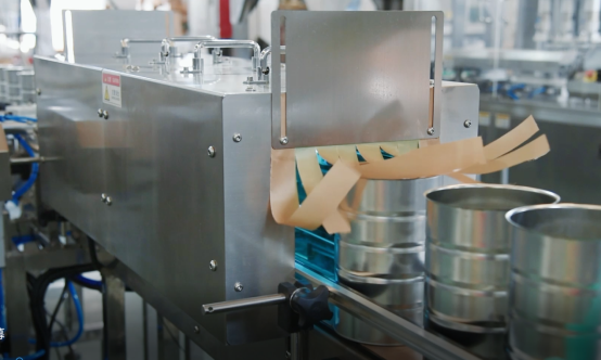
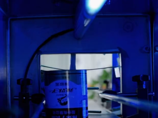
The 75MN horizontal short-stroke front-loading single-action aluminum alloy profile extrusion machine adopts a horizontal three-beam and four-column prestressed composite frame structure, a forward extrusion method, direct drive by an oil pump, and is equipped with advanced foreign electromechanical and hydraulic control components and systems, and The complete set of mechanized auxiliary equipment adopts PLC and computer two-level control to accurately control the speed, position and pressure of the press. The technology used embodies the development trend and advanced technology level of contemporary extrusion presses, and is suitable for production. Manufacturing, operation and maintenance are conducive to improving production efficiency and reducing usage costs.

Prestressed composite frame

The stress-bearing frame of the Aluminum extrusion machine body consists of an integral front beam ZG35Mn (thickness 1950mm) and a rear beam thickness 1800mm (materialZG35Mn), square prestressed sleeve (material ZG35) is a closed prestressed composite frame. Special hydraulic preloading tools are used to pull the An over-pressure tensile load is applied to the entire length of the rod, and compressive stress is applied to the pressure sleeve at the same time, so that the entire frame is in a stress pre-tightened state.The column prestress is above 115% of the maximum load.

(1) The center distance of the four stressed tie rods of the frame is symmetrical to the center of the press, so that the entire frame is stressed evenly. This can increase the squeeze

Accuracy of pressed products.

(2) Since the frame has a large bending resistance section, under the action of extrusion force, the frame elongation and bending deformation are small, so it is the frame can be fixed with horizontal and vertical guide rails at the bottom of the extrusion beam and extrusion barrel.

The centering adjustment is very convenient, and the upper frame can be used as an X-shaped moving guide rail for the extrusion barrel.

(3) There are two sets of elastic anchoring devices and foundation anchors at the lower part of the rear beam to make the rear beam fixed reliably.

Main working cylinder/side cylinder

1. The main working cylinder of aluminum extrusion press is a plunger cylinder, which is fixed to the center of the rear beam through four pressing blocks. The plunger diameter is Φ1740mm, and the medium pressure is 28Mpa. Under the action, it can produce 66.55MN extrusion force. The cylinder body is made of 20MnMo forged steel. After forging and tempering treatment in three sections, it is buried Arc narrow gap welding, processed according to GB\T6402\2008 II level flaw detection. The main plunger is made of forged steel. The outer surface Stainless steel cladding is welded to 2Cr13 with medium frequency treatment, surface hardness is HRC46~48, and polishing degree is 0.2um. V-ring used for master cylinder seal Combined seal, using copper sleeve inner guide

2. The two main side cylinders are horizontally fixed on both sides of the rear beam main working cylinder. The diameter of the side cylinder is Φ450/Φ320mm, which generates an extrusion force of 8.9MN and a return force of 4.4MN, which can realize the rapid forward, backward and extrusion of the main plunger. The cylinder block and piston rod are made of 45 forged steel quenched and tempered. The two-way seal and piston rod seal of the combined piston head adopt V-ring combined seals, and are guided by copper sleeves.

Hydraulic transmission and control system pump station

The pump station of the Aluminum extrusion press adopts an integrated design and is centrally arranged under the rear part of the oil tank of the press. It is composed of an imported German Rexroth electro-hydraulic proportional control axial piston variable pump and a Chinese-made stainless steel plate circulation filtration and cooling system. The piping system design adopts necessary buffering and anti-shock measures, such as cushioning pads, hoses or shock-absorbing hoses, and flexible rubber pipe joints that can absorb vibration. The main system consists of 10 355L/min plunger pumps and 10 320L/min vane pumps from the German REXROTH company. They are designed to be arranged and matched in a certain combination. They can generate a pressure of 28Mpa and a flow rate of 3350L/min to meet the needs of main and side work. According to the cylinder operating speed requirements, closed-loop adjustment of the extrusion speed of 0~21mm/s is achieved, and the extrusion barrel locking cylinder is matched with a dedicated oil pump. Isolation control valves are designed between each oil pump group. If the two mechanisms need to operate at the same time according to the program, they can not interfere with each other. It can realize functions such as isolation between pumps, no-load starting, pressure regulation and overload protection. The pump head electro-hydraulic proportional valve and electronic control device are imported with the main pump and connected with the press main control computer to achieve online control. The main oil cylinder, auxiliary oil cylinder, spindle cylinder, and scissor oil cylinder are integratedly controlled by logic valves. The sliding mold and supporting frame are integratedly controlled by three-position four-way electro-hydraulic reversing valves. Main hydraulic components: master cylinder reversing surface valve, overflow surface valves etc. The main control system oil pump station has a total flow rate of 3350L/min, and its oil pumps are individually controlled.

The design of each aluminum extrusion machine is to maximize the use of resources under the premise of ensuring quality, and has been in a leading position in the industry.

What is an automatic UV sterilizer and its application?

An automatic UV sterilizer is a machine that utilizes ultraviolet light to kill bacteria. It has such as high efficiency, safety, and environmental friendliness. It is suitable sterilization treatment of various bottled and canned food, beverages, medicines, and other products. It can eliminate microorganisms such as bacteria, viruses, and parasites to ensure the quality and safety of the products.

UV sterilizer

The scientific principle behind UV disinfection mainly targets the DNA of microorganisms, disrupting their DNA and rendering them unable to reproduce and replicate, thus achieving the purpose of sterilization and disinfection.


The machine typically consists of a conveyor belt, UV sterilization lamps, and a control system. During operation, bottled or canned products enter the sterilization chamber via the conveyor belt, and the UV sterilization lamps irradiate the surfaces of the products, killing the microorganisms present. The entire sterilization process is conducted in a closed environment, ensuring the hygiene and quality of the products.


The automatic UV sterilizer has the following advantages:


  • Efficient sterilization: Ultraviolet light possesses high energy and penetration, capable of killing various microorganisms, including bacteria, viruses, and parasites.


  • Safety and environmental friendliness: UV sterilization does not produce chemical residues and is harmless to the environment and human health. However, when used in non-sealed conditions, it can still be harmful to the human body. Please pay attention to safety and use with caution.


  • Easy operation: The machine is equipped with an intelligent control system that enables automated operation and monitoring, thereby improving production efficiency.


  • Strong adaptability: The UV sterilization machine is suitable for products of different shapes and sizes. The position and quantity of the sterilization lamps can be flexibly adjusted.

UV sterilization machine

In practical applications, the equipment can be used for sterilizing surfaces and air, and it is widely applied in multiple fields such as powdered milk processing plants, food factories, cosmetics factories, dairy farms, breweries, beverage factories, and bakeries.


As people's demands for food health and quality continue to rise, the application of automatic UV sterilization machines will become increasingly widespread. Utrust pack has been committed to research and innovation in the field of food can packaging, adhering to the concept of "beyond needs, we aspire for deeds" and continuously making higher-quality can packaging solutions for customers.

What kind of design cooling fan can read the tach signal through GPIO?

Typically, the cooling fan is connected to the system through a three-wire interface, which includes a power cable, a ground cable, and a Tach cable (speed signal cable). In order to be able to read Tach signals through GPIO, you need to select a fan that supports this feature. Such fans are often referred to as "ach-enabled" (supporting Tach) or "RPM-sensing" (supporting speed detection) fans.

The Tach signal is a pulse signal whose frequency is proportional to the speed of the fan. Typically, a pulse signal is generated for each rotational speed cycle. Here are some steps to help you implement a cooling fan that reads Tach signals via GPIO:

exhaust fan

1, Make sure that the fan you choose supports Tach function or speed detection function. You can find this information in the fan specifications and instructions.


2. Connect the Tach wire of the fan to the available GPIO pin. This usually requires the use of cables or connectors.


3, Use the appropriate hardware interface circuit to convert the fan's Tach signal into a digital signal that can be read. This is because GPIO typically operates at the digital signal level.


At Chungfo Electronic Technology Co., LTD., we not only provide high quality waterproof exhaust fans, but also various sizes small exhaust fan price are affordable . It can't be ignored that our brushless exhaust fans not only have excellent performance, but also energy saving and environmental protection.

What Is The Principle Of SEM?

Scanning Electron Microscopy (SEM) is based on the principle of using a focused beam of high-energy electrons to probe the surface of a sample and produce a high-resolution detailed image.


Electron Source: SEM works by using an electron source, typically a heated tungsten filament or a field emission gun, to produce a beam of electrons.


Electron Beam Generation: The electron source emits electrons, which are accelerated to high energies by an electric field. The electrons are focused into a narrow beam using electromagnetic lenses.


Sample Interaction: The primary electron beam is directed onto the sample's surface. When the beam interacts with the sample, several types of interactions occur, including scattering, absorption, and emission of secondary electrons.


Scattering: The primary electrons may undergo elastic or inelastic scattering while interacting with the atoms in the sample. Elastic scattering results in a change in direction of the electron beam, while inelastic scattering leads to energy loss due to interactions with the sample's atoms.


Secondary Electron Emission: Some of the primary electrons knock off secondary electrons from the surface of the sample through inelastic scattering. These secondary electrons carry information about the sample's topography and composition.


Signal Detection: The emitted secondary electrons, along with other signals such as backscattered electrons and characteristic X-ray emissions, are detected using various detectors. Some common detectors in SEM are the Everhart-Thornley detector for secondary electrons and detectors for backscattered electrons or X-rays generated by the sample.


Image Formation: The detected signals are then amplified and processed to form an image. The signal intensity is typically converted into a grayscale or false-color representation, allowing the visualization of surface features and details.


Scanning: To generate a complete image, the electron beam is systematically scanned across the surface of the sample in a raster pattern. The intensity of the detected signals at each point is recorded, allowing the construction of a high-resolution image.


Image Display and Analysis: The final reconstructed image is displayed on a monitor or recorded for further analysis. SEM images can be used to examine the microstructure, morphology, elemental composition, and surface characteristics of a wide range of materials.


In short, scanning electron microscopy utilizes the interaction of a focused, high-energy electron beam with a sample to generate detailed images. By analyzing the signals emitted by the sample, SEM provides valuable information about the surface topography, morphology, and composition of the sample at high resolution. It is widely used in a variety of scientific and industrial applications for research, quality control, and materials characterization.


CIQTEK offers various high-quality SEM equipment for researchers and industrial users.


Scanning Electron Microscope Detectors

The Scanning Electron Microscope (SEM) is a powerful tool for various applications in material sciences, life sciences, and other fields. Different kinds of detectors have been developed to obtain more information and improve the performance of SEM. The following are a few common types of SEM detectors:


Backscattered Electron Detector (BSE): BSE detectors are used to detect electrons scattered by the nuclei of atoms and high atomic number elements within a substance.BSE detectors provide high-contrast images that can be used for compositional analysis of materials and characterization of microstructures.


Secondary Electron Detector (SE): The SE detector is used to detect secondary electrons on the surface of a material excited by a scanning electron beam. Since the surface morphology and material composition influence the secondary electrons, the SE detector provides a high-resolution image of the surface topography.


Transmission Electron Detector (TED): TED detectors are used to detect transmission electrons that pass through a thin sheet of material and are focused on the detector. TED detectors are suitable for high-resolution compositional and structural analyses of materials, e.g., atomic-level characterization of nanoparticles.


Energy Dispersive X-ray Spectroscopy (EDS): EDS detectors are used to analyze the elemental composition of materials. When a scanning electron beam interacts with a sample, characteristic X-rays are produced, and the EDS detector collects and measures the energy spectrum of these X-rays to determine the chemical composition and elemental distribution of the material.


Retarding Field Detector (RFD): The RFD detector is used to measure the charge carried by electrons generated on the surface of the sample. This type of detector is very useful for studying the electrical conductivity and surface charge properties of materials.


These are just some of the common SEM detectors; in fact, there are many other types of detectors, each with different advantages and applications. The selection of the appropriate detector depends on the objectives of the study and the information to be obtained.


CIQTEK's self-developed SEM offers a wide range of detectors to choose from, such as BSED, STEM, EDS, EDX, EBSD, In-lens, ETD, etc. 


Why ESR Is Also Known As EPR?

ESR (Electron Spin Resonance) and EPR (Electron Paramagnetic Resonance) are used interchangeably to describe the same spectroscopic technique. The reason for the two different names can be traced to the historical development of the field and some of the interesting stories surrounding it.


Originally, the technique was called ESR, or electron spin resonance. It was discovered in the mid-20th century by physicists studying the behavior of electrons in magnetic fields. They observed that certain materials absorbed energy at specific frequencies when exposed to strong magnetic fields and subjected to electromagnetic radiation. This absorption is due to the electron spin states flipping in the magnetic field, resulting in resonance.


As the field grew, researchers began to study the spectra of paramagnetic species - atoms, molecules, or ions with unpaired electrons. They realized that ESR techniques could be used to study a wider range of systems than just electrons. As a result, the term EPR (Electron Paramagnetic Resonance) was coined to encompass a broader range of applications.


The transition from ESR to EPR did not happen overnight or with universal adoption. Different research groups and scientific communities preferred to use either term. For example, the term ESR was widely used in the United States, while EPR became popular in Europe. This difference in naming conventions continued for some time until the two terms gradually became synonymous. Today, the two terms are widely accepted and used interchangeably to describe the same spectroscopic techniques.


The dual naming of ESR and EPR provides insight into the historical development of the field and how scientific terminology has evolved and adapted over time. It also serves as a reminder that in science, different cultures and communities may adopt different names for the same concept, and these differences may persist until a consensus is reached.


EPR spectroscopy has applications in a variety of fields including chemistry, physics, biochemistry, materials science, and medicine. It has been used to study the structure of metalloproteins, the mechanism of enzyme reactions, the properties of organic radicals, the behavior of transition metal complexes, and defects in semiconductors, as well as many other fascinating areas of research. Its ability to probe electron spin makes it an invaluable tool for understanding the fundamental properties of paramagnetic systems and exploring their role in a variety of physical and chemical processes.

>> Check more about CIQTEK EPR spectroscopy.

CIQTEK EPR spectroscopy